View of the ruptured cylinder in the as-received condition. A primarily axial rupture split the cylinder wide open. The axial fracture turned circumferential in opposing directions at the base of the cylinder. The two fracture halves are labeled “A” and “B” for examination identification purposes. The green arrows indicate the rupture initiation site. The smaller black arrows indicate the direction of fracture propagation.

Failure Analysis of Ruptured Inergen Fire Suppression Cylinder

December 22, 2023

Background

A ruptured cylinder from a fire suppression system was received by the Rimkus Materials Testing and Investigation team for analysis to determine the cause of failure. The cylinder was filled with an INERGEN (52% nitrogen, 40% argon, and 8% carbon dioxide) mixture at approximately 2300 psi at the time of rupture event.

Services Provided

Rimkus experts performed a series of testing and analytical techniques on the ruptured cylinder to provide a full failure analysis report to the client. These tests and services included the following:

  • Visual, stereoscopic, and scanning electron microscope (SEM) examinations
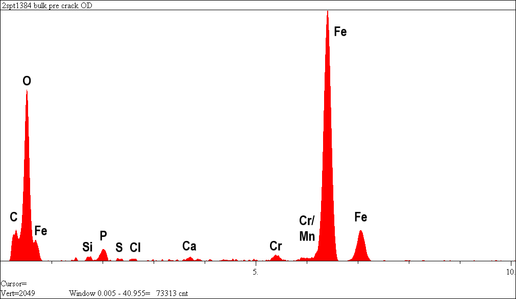
  • Elemental analysis (EDS)
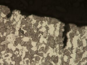
  • Metallography (microstructure evaluation)
  • Chemical composition (OES)
  • Tensile testing and hardness

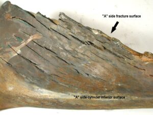
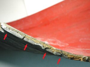
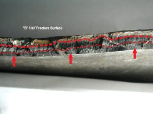
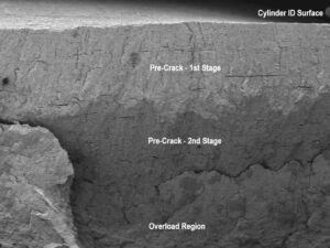
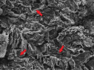
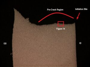
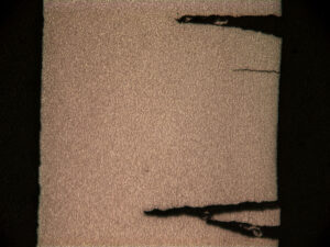
Results indicate the rupture initiated at a longitudinal alignment of several pre-existing axial cracks on the cylinder’s interior. The pre-existing cracks were characterized by black oxide-covered, arc-shaped crack fronts initiating from the interior surface and penetrating approximately 50% – 80% through the cylinder wall. The presence of black oxide indicates the cracks have been present for a long period of time and may have occurred at a high temperature during manufacturing thermal processing. Black oxide may also be a result of corrosion along the pre-existing cracks in a low oxygen environment.

There was evidence of two stages of crack progression before the rupture; however, the time between the stages could not be determined. Black oxide and significant corrosion along the crack lengths were exhibited in both regions. The second stage of crack progression appeared to have been either very old or occurred over a long period of time.

The black oxide on the pre-crack surfaces indicates the cracks have been present for a long period of time and may have occurred at high temperature during manufacturing thermal processing. Black oxide may also be a result of corrosion along the pre-existing cracks in a low oxygen environment.

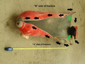
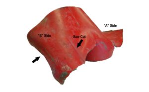
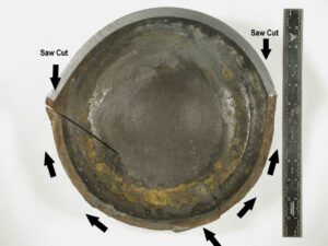
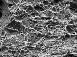
Numerous long-term, pre-existing axial cracks were similarly noted near the rupture site. The observed pre-existing internal cracks were limited to within approximately 18 inches (0.5 meters) of the tank bottom. Shallow, pre-existing circumferential cracks were observed on the circumferential fracture surface along the tank bottom. These were a continuation of the axial rupture at the bottom of the cylinder (see Figure 1). There appeared to have been active corrosion along the pre-existing cracks. The remainder of the fracture surface (beyond the pre-existing crack zones) exhibited features indicative of rapid ductile overload.

Other than the pre-existing cracks, no other unusual conditions were found in the cylinder microstructure. The cylinder material meets the Department of Transportation 178.37 Specification 3AA and 3AAX seamless steel cylinders for chemical composition. The cylinder steel exhibited a yield strength of 74,700 psi and an ultimate tensile strength of 105,100 psi.

Photos

View of the ruptured cylinder in the as-received condition. A primarily axial rupture split the cylinder wide open. The axial fracture turned circumferential in opposing directions at the base of the cylinder. The two fracture halves are labeled “A” and “B” for examination identification purposes. The green arrows indicate the rupture initiation site. The smaller black arrows indicate the direction of fracture propagation.
Figure 1: View of the ruptured cylinder in the as-received condition. A primarily axial rupture split the cylinder wide open. The axial fracture turned circumferential in opposing directions at the base of the cylinder. The two fracture halves are labeled “A” and “B” for examination identification purposes. The green arrows indicate the rupture initiation site. The smaller black arrows indicate the direction of fracture propagation.


Second view of the as-received ruptured cylinder. The cylinder was sectioned approximately across the dashed line for easier handling and examination.
Figure 2: Second view of the as-received ruptured cylinder. The cylinder was sectioned approximately across the dashed line for easier handling and examination.


A close up photo of fracture side “A” near the cylinder bottom. The axial fracture surface displays multiple jogs resembling a stair-step appearance. The interior (ID) surface exhibits numerous cracks. These features are shown in closer views in subsequent figures.
Figure 3: A close up photo of fracture side “A” near the cylinder bottom. The axial fracture surface displays multiple jogs resembling a stair-step appearance. The interior (ID) surface exhibits numerous cracks. These features are shown in closer views in subsequent figures.


View of the interior surface of the cylinder along the rupture on side “A” exhibits numerous longitudinal cracks. The ID cracks opened during the rupture event. All of the cracks are within approximately 18 inches (46 cm) of the cylinder bottom.
Figure 4: View of the interior surface of the cylinder along the rupture on side “A” exhibits numerous longitudinal cracks. The ID cracks opened during the rupture event. All of the cracks are within approximately 18 inches (46 cm) of the cylinder bottom.


Close-up view of the “A” side axial fracture surface approximately 8 inches. (20 cm) from the tank bottom reveals black oxide covered arc-shaped crack fronts (arrows) indicating pre-existing cracks in the fracture surface.
Figure 5: Close-up view of the “A” side axial fracture surface approximately 8 inches. (20 cm) from the tank bottom reveals black oxide covered arc-shaped crack fronts (arrows) indicating pre-existing cracks in the fracture surface.


EDS analysis of the black oxide deposit near the tip of the pre-existing crack region (mid-wall) on the “A” side axial fracture surface. Mostly iron oxide with traces of carbon, phosphorous, sulfur, chlorine and calcium are present. The chromium and silicon content are attributed to the cylinder steel.
Figure 6: EDS analysis of the black oxide deposit near the tip of the pre-existing crack region (mid-wall) on the “A” side axial fracture surface. Mostly iron oxide with traces of carbon, phosphorous, sulfur, chlorine and calcium are present. The chromium and silicon content are attributed to the cylinder steel.


View of the cut-off cylinder bottom on the “B” side. The black arrow identifies an area where the fracture surface is shown in a close-up view in Figure 8.
Figure 7: View of the cut-off cylinder bottom on the “B” side. The black arrow identifies an area where the fracture surface is shown in a close-up view in Figure 8.


The “B” side axial fracture surface after cleaning reveals black oxide covered pre-existing crack patterns along the cylinder ID surface, extending across approximately 80% of the cylinder wall. A slight variation in the black deposit suggests a two-stage pre-crack (between dashed lines).
Figure 8: The “B” side axial fracture surface after cleaning reveals black oxide covered pre-existing crack patterns along the cylinder ID surface, extending across approximately 80% of the cylinder wall. A slight variation in the black deposit suggests a two-stage pre-crack (between dashed lines).


A view of the circumferential fracture at the cylinder bottom revealed after sectioning. The bottom internal surface displays some corrosion (brown staining). The fracture propagation direction is indicated by the arrows.
Figure 9: A view of the circumferential fracture at the cylinder bottom revealed after sectioning. The bottom internal surface displays some corrosion (brown staining). The fracture propagation direction is indicated by the arrows.


Low magnification SEM image of the inhibited acid cleaned “B” side axial fracture surface. The narrow slits in the fracture surface are sulfide stringers that have been preferentially corroded. The discoloration suggests two stages of crack propagation before rupture.
Figure 10: Low magnification SEM image of the inhibited acid cleaned “B” side axial fracture surface. The narrow slits in the fracture surface are sulfide stringers that have been preferentially corroded. The discoloration suggests two stages of crack propagation before rupture.


High magnification SEM image of the “A” side opened crack in the second stage pre-crack tip region also reveals a corroded surface with hints of some intergranular features (arrows).
Figure 11: High magnification SEM image of the “A” side opened crack in the second stage pre-crack tip region also reveals a corroded surface with hints of some intergranular features (arrows).


High magnification SEM image reveals a dimpled morphology (micro-void coalescence) at the location of ductile overload, resulting from opening the secondary crack.
Figure 12: High magnification SEM image reveals a dimpled morphology (micro-void coalescence) at the location of ductile overload, resulting from opening the secondary crack.


Low magnification optical photomicrograph of the “A” side transverse cross-section through the rupture initiation region. The ID initiation site is identified at the arrow. The pre-existing crack zone is indicated. The OD side has yielded. The boxed areas are displayed at increased magnification in subsequent figures as indicated.
Figure 13: Low magnification optical photomicrograph of the “A” side transverse cross-section through the rupture initiation region. The ID initiation site is identified at the arrow. The pre-existing crack zone is indicated. The OD side has yielded. The boxed areas are displayed at increased magnification in subsequent figures as indicated.


High magnification photomicrograph of the unetched cross-section along the fracture surface reveals axial corrosion penetrations, indicating active corrosion along the pre-existing crack.
Figure 14: High magnification photomicrograph of the unetched cross-section along the fracture surface reveals axial corrosion penetrations, indicating active corrosion along the pre-existing crack.


Low magnification photomicrograph of the transverse cross-section across several of the internal secondary cracks. The cracks have widened during rupture.
Figure 15: Low magnification photomicrograph of the transverse cross-section across several of the internal secondary cracks. The cracks have widened during rupture.

Sorry, no posts matched your criteria.